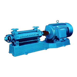
D type clean water multistage pump

Product overview
D type horizontal multistage pump is a piecewise single suction multistage centrifugal pump. For conveying clean water or other liquids similar in physical and chemical properties to water. It can also be used to transport hot water, oil, corrosive or abrasive media by changing the material of the pump flow parts, sealing form and increasing the cooling system. Product implementation of JB/T1051-93 “multi-stage water centrifugal pump type and basic parameters” standard.
Second, product characteristics
It has the characteristics of high efficiency, wide performance range, safe and stable operation, low noise, long life, convenient installation and maintenance, etc
Main Application
1, municipal drainage, high-rise building water supply.
2, industrial drainage, pressurized drainage, circulating water, pipeline water or other media.
3, agricultural irrigation, mountain water.
4, fire water supply, stable pressure water supply.
5, flushing, flushing equipment water.
Model Implication
D 25 minus 50 X 8
D- Horizontal multistage centrifugal pump
25- The design point flow of the pump is 25m3/h
50- The design point head of the pump is 50m
8- The pump is a stage 8
Five, Performance Parameters
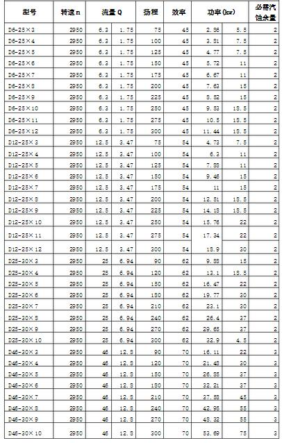
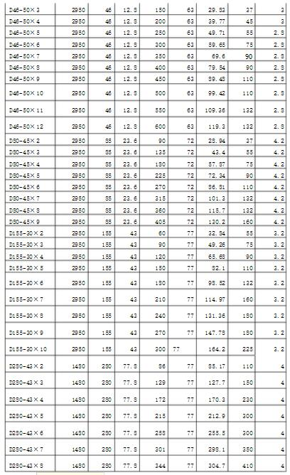
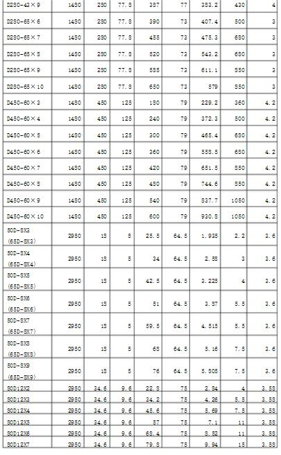
Technical Parameters:
Maximum flow -Qmax=850m3/h
Maximum head -Hmax=1800m
Running speed- nmax=2950rpm
running temperature- t≤102℃
D type horizontal multistage pump structure description
1. the overall structure of multi-stage segment, the intake is located in the water inlet section, into the horizontal direction, the spit outlet in the water section vertically upward, its head can be according to the use of the need to increase or decrease the pump series. The pump assembly is good or not, has a great impact on the performance, especially the outlet of each impeller and the inlet and outlet center of the guide wing. A slight deviation will reduce the flow of the pump and reduce the head efficiency. Therefore, attention must be paid to the maintenance and assembly.
2. The main parts are: inlet section, middle section, outlet section, impeller, guide wing baffle, outlet section guide wing, shaft, seal ring, balance ring, shaft sleeve, tail cover and bearing body.
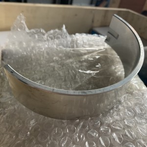
3. the impeller is made of high quality cast iron, with blades, liquid enters along the axial direction, because the impeller before and after the pressure is different, there must be axial force, the axial force by the balance plate to bear, the impeller manufactured by the static balance test.
4. The sealing ring is made of cast iron to prevent the high-pressure water of the pump from leaking back to the inlet part. It is fixed on the inlet section and the middle section respectively.
5. The balance plate is made of wear-resistant cast iron, mounted on the shaft, located between the outlet section and the tail cover, to balance the axial force.
6. bearings for rolling bearings, the use of Guoyou (Havallo) brand.
1.Preparations before installation.
1) Check the water pump and motor.
2) Prepare tools and lifting machinery.
3) Check the foundation of the machine.
2. Installation sequence:
1) the whole set of water pump to the site, with the base has been installed motor, leveling the base inch can not be removed from the pump and motor.
2) Place the base on the foundation, place the wedge iron near the anchor screw, and raise the base about 20? 40mm, ready to be leveled and filled with water screw slurry.
3) Check the levelness of the base with a level instrument, level it and then tighten the foundation nut to fill the base with cement slurry.
4) after 3 or 4 days of cement dry, and then check the level.
5) Clean the dirt on the support plane of the base, the water pump foot and the motor foot; And put the pump and motor on the base
6) Adjust the level of the pump shaft, tighten the nut properly after leveling to prevent walking, install the motor after the adjustment is completed, and pad the iron plate at the inappropriate level.
7) put the ruler on the coupling, check whether the pump axis line and the motor axis line coincide. If there is no heavy table, pad the motor or pump at the foot of the sheet, so that the outer circle of the two coupling is flat with the ruler, and then take out a few thin iron sheets of the pad, replace the iron sheet with the whole planed iron plate, and recheck the installation. In order to check the accuracy of the installation, measure the clearance between the two coupling planes with a gauge in several opposite positions. The difference between the maximum and minimum clearance on the coupling plane should not exceed 0.3 mm, and the difference between the upper and lower or left and right centerlines at both ends should not exceed 0.1 mm.